The MPU6050 Explained
Introduction
This article will explain how to use the data coming from an MPU6050 device by using C++ code examples and some illustrative diagrams. The MPU6050 is an Inertial Measurement Unit (IMU) that combines a MEMS gyroscope and accelerometer and uses a standard I2C bus for data communication. I’ll sometimes use the term IMU in reference to the MPU6050 in this article. There are many great articles that explain the basic concepts of gyroscopes and accelerometers, one of the best ones I’ve found is on the CH Robotics site. I’ve used some of the images from that site in this article. There’s also a great introductory video explaining the MPU6050 on the Dronebot Workshop over here.
The mechanical part of an MPU6050 is shown in the following photo.


Yes, it’s microscopic! But a much larger diagram of the accelerometer will help show what’s going on.
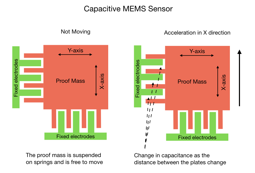
What’s referred to as the Proof Mass is suspended on springs and is free to move around as the device undergoes acceleration. The fixed comb of electrodes sets up a capacitive effect between itself and the proof mass. As the device moves a change in capacitance is recorded and converted by an ADC to a digital value between 0 and 32,750. The gyroscope functions in a similar way except that it works on the Coriolis Effect instead of acceleration.
The result is that the MPU6050 is going to throw a bunch of numbers at you, and you need to interpret them for use in your project. The rest of this article will hopefully help you make sense of these numbers.
Device Sensitivity
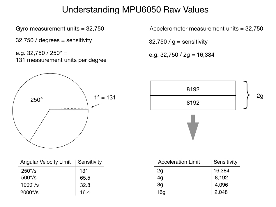
As just mentioned, the analog voltage read from the capacitive sensors is converted to digital signal in the range of 0 to 32750 values. These values make up the measurement units for the gyroscope and accelerometer. The measurement units have to be split up to represent meaningful information. The MPU6050 allocates its measurement units by creating four sensitivity levels, as shown in the slide below. The sensitive level that you chose depends on how you’re going to use the IMU. For instance, if the robot is going to do high speed rotations of over 1000° per second (167 RPM) then you should set the gyro sensitivity to 2000°. In this case, since the gyro has to cover a lot of rotational ground in a very short period time it needs to split up its measurement units sparingly. For most applications however, the robot is unlikely to rotate that quickly so we can set the sensitivity level to 250°, which is the default setting. This gives us 131 measurement units per second per degree providing a very high level of precision.
The default setting for the accelerometer is 2g. This should be appropriate for most applications outside of an F14 or a robotic arm building a Tesla.
Code Setup
So let’s start looking at the code required to use the MPU6050. I’ll make use of one of the i2cdev libraries developed by Jeff Rowberg, which significantly simplifies the job of getting data from the MPU6050 device. I installed the example code MPU6050_DMP6 on an Arduino. The code example is a little difficult to understand at first glance, so I’ll go through the key parts of it and try to explain what’s going on. The key parts of the setup code is shown below.
void mpu_setup()
{

  mpu.initialize();
  pinMode(INTERRUPT_PIN, INPUT);

  // verify connection
  Serial.println(F("Testing device connections..."));
  Serial.println(mpu.testConnection() ? F("MPU6050 connection successful") : F("MPU6050 connection failed"));

  // load and configure the DMP
  Serial.println(F("Initializing DMP..."));
  devStatus = mpu.dmpInitialize();

  // supply your own gyro offsets here, scaled for min sensitivity
  mpu.setXGyroOffset(220);
  mpu.setYGyroOffset(76);
  mpu.setZGyroOffset(-85);
  mpu.setZAccelOffset(1788); // 1688 factory default for my test chip

  // make sure it worked (returns 0 if so)
  if (devStatus == 0) {
    // turn on the DMP, now that it's ready
    Serial.println(F("Enabling DMP..."));
    mpu.setDMPEnabled(true);

    // enable Arduino interrupt detection
    Serial.println(F("Enabling interrupt detection (Arduino external interrupt 0)..."));
    attachInterrupt(digitalPinToInterrupt(INTERRUPT_PIN), dmpDataReady, RISING);
    mpuIntStatus = mpu.getIntStatus();

    // set our DMP Ready flag so the main loop() function knows it's okay to use it
    Serial.println(F("DMP ready! Waiting for first interrupt..."));
    dmpReady = true;

    // get expected DMP packet size for later comparison
    packetSize = mpu.dmpGetFIFOPacketSize();
  } else {
    // ERROR!
    // 1 = initial memory load failed
    // 2 = DMP configuration updates failed
    // (if it's going to break, usually the code will be 1)
    Serial.print(F("DMP Initialization failed (code "));
    Serial.print(devStatus);
    Serial.println(F(")"));
  }
}

volatile bool mpuInterrupt = false;     // indicates whether MPU interrupt pin has gone high
void dmpDataReady() {
    mpuInterrupt = true;
}
The initialize( ) command sets the accelerometer to +/- 2g and the gyroscope to 250% per second by default. These are the most sensitive settings. The sensitivity settings were explained in the previous section. The testConnection() will check that it can find the I2C device address associated with the IMU. This should be either 0x68 or 0x69.
The next step is to initialize the Digital Motion Processor (DMP). This is the MPU6050’s onboard processor that combines the data coming from the accelerometer and gyroscope. The DMP is the key to using the the MPU6050 and is explained in detail later.
As with all microprocessors the DMP needs firmware in order to run. The dmpInitialize( ) command loads the firmware and configures it. It also initializes the FIFO buffer that’s going to hold the combined data readings coming from the gyroscope and accelerometer. Providing everything has gone well with the initialization the DMP is enabled.
There are a few statements to provide some default offsets for the gyroscope and accelerometer. I’ll come back to those later in the section about calibration.
The next part of the code that sets up an interrupt was a little confusing at first, since I’d seen many wiring diagrams that don’t show the interrupt pin connected. Turns out that you can use the MPU6050 both with and without the interrupt. If the IMU is being used in projects that require you to send control actions to the robot then it’s probably not desirable to use the interrupt method, since it may be difficult to get the control actions through. At the end of the article I’ll show you how to use MPU6050 without the interrupt (in polling mode). The interrupt just calls a short ISR that sets a flag when the MPU’s data buffer is full. The ISR is shown at the end of the above code sample.
Calibration
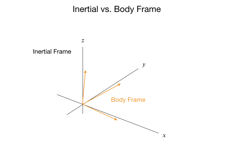
Before using the IMU on a project it has to be calibrated. The IMU as mounted on the robot will not be perfectly aligned with the ground, so you need to take a series of data measurements from the accelerometer and gyroscope to produce offsets. From a physics perspective the offsets provide a translation from the Body Frame to the Inertial Frame. The Body Frame is the IMU mounted on the robot, whereas the Inertial Frame is the frame from which all angle and velocity calculations are done.

There are a few processes that can be use to calibrate the sensors. I’ve had some success with the following process, which uses code written by Luis Ródenas that I found here. After mounting the MPU6050 to the robot you run the code just one time and take note of the final output. The output will be a set of six offset values that you can hard code into your script.
At the beginning of the process all of the accelerometer and gyro offsets are set to zero. We then take 1000 readings from the the IMU and calculate the mean value for each offset. These values are then entered into the IMU to become the new offsets. The calibrate routine will continue to take the mean IMU readings until the calibration is within a certain tolerance. The calibration may take a little time to run depending on the speed of the CPU.
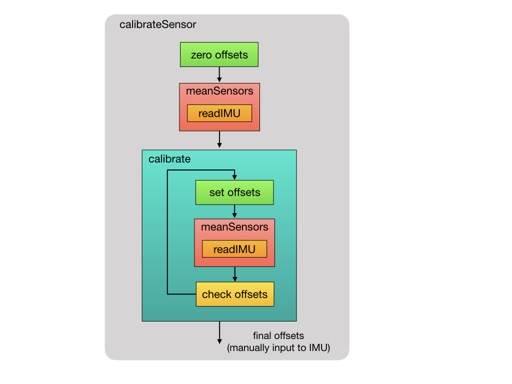
 So let’s take a look at the calibration code that I’m using that was written by Luis Ródenas. The raw acceleration and gyroscope data is read from the IMU. This function is used at multiple points in the calibration process as shown in the diagram above.
//--------------------------------------------//
// Read the raw sensor values
//--------------------------------------------//
void IMU::readIMU() {

  // Using the MotionApps library
  accX = mpu.getAccelerationX();
  accY = mpu.getAccelerationY();
  accZ = mpu.getAccelerationZ();
  gyroX = mpu.getRotationX();
  gyroY = mpu.getRotationY();
  gyroZ = mpu.getRotationZ();
}
The calibration process starts by zeroing out the IMU offsets. An initial 1000 measurements are read from the IMU and the mean values are computed. We then drop into the main calibration routine, which loops until the offsets are within tolerance.
//----------------------------------------------------//
// Calibrate bias of the accelerometer and gyroscope
// Sensor needs to be calibrated at each power cycle.
//----------------------------------------------------//
void IMU::calibrateSensor()
{
  // Initialize the offset values
  setOffsets(0, 0, 0, 0, 0, 0);

  ROSLOGString("Reading sensors for first time...");
  meanSensors_();
  delay(1000);

  ROSLOGString("Calculating offsets...");
  calibrate_();
  delay(1000);
}
The meanSensor( ) routine is shown below. The first 100 readings are discarded and then 1000 measurements are accumulated and divided by the sample size. A delay is inserted to ensure that there are no repeat data readings.
int buffersize=1000;     // Number of readings used to average
//--------------------------------------------//
// Get the mean values from the sensor
//--------------------------------------------//
void IMU::meanSensors_() {

  long i=0,buff_ax=0,buff_ay=0,buff_az=0,buff_gx=0,buff_gy=0,buff_gz=0;

  while (i<(bufferSize+101)) {

    // read raw accel/gyro measurements from device
    readIMU();

    if (i>100 && i<=(bufferSize+100)) { //First 100 measures are discarded
      buff_ax=buff_ax+accX;
      buff_ay=buff_ay+accY;
      buff_az=buff_az+accZ;
      buff_gx=buff_gx+gyroX;
      buff_gy=buff_gy+gyroY;
      buff_gz=buff_gz+gyroZ;
    }
    if (i==(bufferSize+100)){
      mean_ax=buff_ax/bufferSize;
      mean_ay=buff_ay/bufferSize;
      mean_az=buff_az/bufferSize;
      mean_gx=buff_gx/bufferSize;
      mean_gy=buff_gy/bufferSize;
      mean_gz=buff_gz/bufferSize;
    }
    i++;
    delay(2); //Needed so we don't get repeated measures
  }
}
This is the main loop of the calibration process. Look through the code segment, and if you’re still confused about how it works (as I was) then read on.
int acel_deadzone=8;     //Accelerometer error allowed
int giro_deadzone=1;     //Giro error allowed
//--------------------------------------------//
// Calibrate sensor
//--------------------------------------------//
void IMU::calibrate_() {
  ax_offset=-mean_ax/8;
  ay_offset=-mean_ay/8;
  az_offset=(16384-mean_az)/8;

  gx_offset=-mean_gx/4;
  gy_offset=-mean_gy/4;
  gz_offset=-mean_gz/4;
  while (1){
    int ready=0;
    mpu.setXAccelOffset(ax_offset);
    mpu.setYAccelOffset(ay_offset);
    mpu.setZAccelOffset(az_offset);

    mpu.setXGyroOffset(gx_offset);
    mpu.setYGyroOffset(gy_offset);
    mpu.setZGyroOffset(gz_offset);

    // Get the mean values from the sensor
    meanSensors_();
    logMeanValues();

    if (abs(mean_ax)<=acel_deadzone) ready++;
    else ax_offset=ax_offset-mean_ax/acel_deadzone;

    if (abs(mean_ay)<=acel_deadzone) ready++;
    else ay_offset=ay_offset-mean_ay/acel_deadzone;

    if (abs(16384-mean_az)<=acel_deadzone) ready++;
    else az_offset=az_offset+(16384-mean_az)/acel_deadzone;

    if (abs(mean_gx)<=giro_deadzone) ready++;
    else gx_offset=gx_offset-mean_gx/(giro_deadzone+1);

    if (abs(mean_gy)<=giro_deadzone) ready++;
    else gy_offset=gy_offset-mean_gy/(giro_deadzone+1);

    if (abs(mean_gz)<=giro_deadzone) ready++;
    else gz_offset=gz_offset-mean_gz/(giro_deadzone+1);

    if (ready==6) break;
  }
}
At the start, the mean values are taken from the previous step and used to provide initial offset values. In order to get a nicely calibrated system the plan is to make these values as small as possible. Here’s a sample of the initial mean values right after the IMU offsets have been set to zero.
Acclerometer 8531, -31407, 2727
Gyroscope    20, -34, 14
As you can see, there’s still a long way to go, so as a first cut some fraction of the mean values are taken. I’m not sure how the divisors are arrived at, but it does come up with a value that’s somewhat close to the final offset values:
ax_offset -1066
ay_offset 3925
az_offset 1707
gx_offset -5
gy_offset 8
gz_offset -3
Going into the loop, the offset values are input to the IMU and a new set of mean values are taken. With the new offsets the next group of mean values are starting to look much better.
Acclerometer 153, -1084, 16117
Gyroscope    13, -23, 10
Dividing these by the dead zone constants and subtracting it from the current offsets produce new offsets for the IMU:
ax_offset -917
ay_offset 3192
az_offset 1469
gx_offset -13
gy_offset 23
gz_offset -9
Each time the loop runs the mean values get smaller and smaller. So it just keeps going until the mean values are within the allowed error margin, at which point it drops out of the loop and we’re done. If you don’t want to run the calibration routine every time you switch on the robot, then hardcode these offset values into the setup routine of your project.
Getting the Orientation
There are two ways to extract useful data from the MPU6050. One way is to read the raw sensor data values, as we did during calibration process, and use that data to compute the new orientation. The second method is to pull the data out of the MPU’s onboard Digital Motion Processor (DMP). To see the difference between the two methods we can look at an example of how you would get the pitch angle. If you were coding for a balancing robot the pitch angle would be key to keeping the robot upright.
To get the pitch angle using the raw sensor data there are several translations that need to be made.
-
The gyroscope gives the rate of change of the angular position over time, called angular velocity. Therefore, it has to be integrated over a time to get the angle position.
-
Before making any calculations you have to translate readings from the body frame to the inertial frame by using the IMU offsets.
-
You need to convert the raw IMU sensor readings into degrees.
-
To mitigate the effects of drift you need to combine gyro information with readings coming from the accelerometer.
Let’s go though these one by one.
Gyroscopes do NOT report angles, they report the speed at which the device is turning, or angular velocity. In order to get the angle position you have to integrate it over time. The code below shows the time integration being applied to the angular rate information coming from the gyroscope.
To bring the body frame of the robot into the inertial frame you have to subtract the offsets. The offset values were calculated during the calibration process. If you’re going to use the raw sensor data then these offset values have to stored in your program variables.
The raw sensor readings need to be converted into degrees prior to applying the integration. This is done by dividing the readings by the sensitivity measurement unit. Recall that at the highest sensitivity setting each degree is represented by 131 measurement units.
//--------------------------------------------//
// Get angle from the gyroscope. Uint: degree
//--------------------------------------------//
float IMU::getGyroRoll(int gyroX, int gyroBiasX, uint32_t lastTime)
{
  float gyroRoll;

  //integrate gyroscope value in order to get angle value
  gyroRoll = ((gyroX - gyroBiasX ) / 131) * ((float)(micros() - lastTime) / 1000000);
  return gyroRoll;
}
The following code shows how you would calculate the pitch angle coming from the accelerometer. The formulas for computing the angles for yaw, pitch, and roll can be found online. Again, you need to subtract the offset values. The resulting output is in radians, which need to be converted into degrees.
//-----------------------------------------------//
//Get angle from the accelerometer. Uint: degree
//-----------------------------------------------//
float IMU::getAccRoll(int accY, int accBiasY, int accZ, int accBiasZ)
{
  float accRoll;

  //calculate angle value
  accRoll = (atan2((accY - accBiasY), (accZ - accBiasZ))) * RAD_TO_DEG;

  if (accRoll <= 360 && accRoll >= 180) {
    accRoll = 360 - accRoll;
  }
  return accRoll;
}
After computing the pitch angles coming from the accelerometer and the gyroscope a Complementary Filter is used to the mitigate the vibration effects that the accelerometer is subjected to and, more importantly, the long term drift effects of the gyroscope.
So where does drift come from? As just mentioned, gyroscopes do not report angles, they report the speed at which the device is turning. In order to get the angle position you have to integrate it over time. You may remember from your calculus class that to get position you have to integrate velocity. Since the time period used on a computer has some defined length, like 10 milliseconds, the integration process introduces a small error in the position calculation. The accumulation of these small errors over time is what causes drift. Of course, the smaller you make the time periods the less drift you get, but eventually you run into the limits of the CPU speed.
The Complementary Filter calculation is shown in the code below. More information about complementary filters, and how to tune them, can be found online. Since mitigating gyro drift is our primary objective the code shows the filter being heavily weighted in that direction.
//--------------------------------------------//
// Get current angle of the robot
//--------------------------------------------//
float IMU::currentAngle() {

  // Get raw IMU data
  readIMU();

  // Complementary filter for angle calculation
  float gRoll = getGyroRoll(gyroX, gx_offset, lastTime);
  float aRoll = getAccRoll(accY, ay_offset, accZ, az_offset);

  float angleGet = 0.98 * (angleGet + gRoll) + 0.02 * (aRoll);

  lastTime = micros(); // Reset the timer

  return angleGet;
}
Using the Digital Motion Processor (DMP)
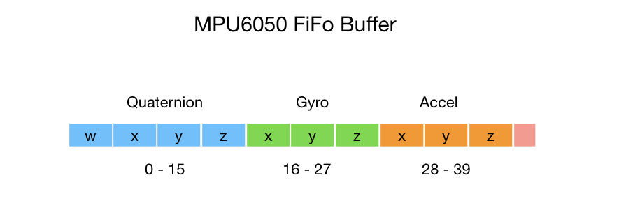
So that’s a lot of work in order to get the pitch angle! Let’s look at how you would get the pitch angle using the MPU6050’s onboard Digital Motion Processor. The DMP offloads processing that would normally have to take place on the microprocessor. It maintains an internal buffer that combines data from the gyro and accelerometer and computes orientation for you. The DMP also takes care of the applying the offsets, so you don’t have to keep track of these in your project code. Here’s the format of the DMPs internal FiFo buffer.
To read the DMP’s buffer into your program you can use the following sequence of statements. The interrupt status is checked and the buffer is read into your local program variable. Once that’s done, the orientation information can be accessed.
// Check for DMP data ready interrupt (this should happen frequently)
if (mpuIntStatus & 0x02) {

	 // wait for correct available data length, should be a VERY short wait
	 while (fifoCount < packetSize) fifoCount = mpu.getFIFOCount();

   // read a packet from FIFO
   mpu.getFIFOBytes(fifoBuffer, packetSize);

   // track FIFO count here in case there is > 1 packet available
   // (this lets us immediately read more without waiting for an interrupt)
   fifoCount -= packetSize;

     // get quaternion values in easy matrix form: w x y z
   mpu.dmpGetQuaternion(&q, fifoBuffer);
}
The orientation is represented by a Quaternion. Quaternions are a way to represent the orientation of an object in 3D space and can be efficiently calculated on a computer. They also avoid a problem that occurs when you rotate through an angle of more that 90°, called Gimbal Lock. Unless you are working on a drone project you probably won’t run into the Gimbal Lock problem so you can safely ignore it. Quaternions are somewhat difficult to understand which is why they were ignored in favor of Euler angles for over 100 years. But if you’re serious about working with robotics you can’t ignore the subject of Quaternions for too long. There are many online resources for learning Quaternions but I’ll give one visualization that I found useful.
Quaternions
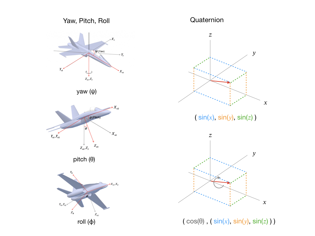
To understand Quaternions it’s useful to compare them to Yaw, Pitch, Roll, which is a concept that most people are more familiar with. To represent a change in orientation you first specify the Yaw angle, which is a rotation around the z-axis. Then add the Pitch, which is a rotation around the y-axis. And finally a Roll around the x-axis. Of course, a plane may do this in a different order, or more likely all at once, but the end result is still a change in orientation. The key here is that you only need three parameters (ψ, θ, ϕ) to represent the transformation.
Contrast this with a Quaternion that inexplicably requires four parameters. So a Quaternion is first going to use a vector and point it in the direction that you need to go. This is represented by the red arrow in the diagram below, and is always one unit in length. Since the arrow can point anywhere is 3D space we need three parameters to define it. The direction parameters are given as sines. Once we have a direction, we can execute a roll to get us to the final orientation. That’s the purpose of the forth parameter. It specifies in degrees (or radians) how much we need to rotate.

To ensure that the orientation data is useful for all applications the DMP stores its computations as Quaternions. Jeff Rowberg’s program gives you an easy way to convert the Quaternions to other useful information such as Euler angles and linear acceleration.
Euler Angles
Once we’ve retrieved data from the DMP we can use it to get Euler angles. The Quaternion values are passed into the dmpGetEuler( ) function to transform them to Euler angles. The output is given in radians so a conversion to degrees can be done if required. The formula for converting Quaternions to Euler angles can be found online, or by examination of Jeff Rowberg’s library.
mpu.dmpGetQuaternion(&q, fifoBuffer);
mpu.dmpGetEuler(euler, &q);

float psi = euler[0] * 180/M_PI;
float theta = euler[1] * 180/M_PI;
float phi = euler[2] * 180/M_PI;
Euler angles are much easier to understand than Quaternions and for some applications Euler angles are preferable. Check online to learn more about them. Euler angles are specified as a pure change in orientation without regard to gravity.
Yaw, Pitch, Roll
As you saw earlier, calculating pitch information required a bit of programming. Contrast this with getting pitch from the DMP, which can be done in four statements. The gravity components first need to be extracted out of the precomputed Quaternions data. The gravity is then passed into a function to get the pitch.
mpu.dmpGetQuaternion(&q, fifoBuffer);
mpu.dmpGetGravity(&gravity, &q);
mpu.dmpGetYawPitchRoll(ypr, &q, &gravity);

float pitch = ypr[1] * 180/M_PI;
Acceleration
Acceleration data is also available in the DMP’s buffer. However, as the IMU is moving the force being reported by the accelerometer is not only the earth’s force but also the force causing it to accelerate. Therefore, you need remove gravity from the calculation in order to get the linear acceleration. As mentioned previously, the gravity components can be extracted from the Quaternions, so we use those together with the acceleration readings to compute linear acceleration.
// display real acceleration, adjusted to remove gravity
mpu.dmpGetQuaternion(&q, fifoBuffer);
mpu.dmpGetAccel(&aa, fifoBuffer);
mpu.dmpGetGravity(&gravity, &q);
mpu.dmpGetLinearAccel(&aaReal, &aa, &gravity);
float x = aaReal.x;
float y = aaReal.y;
float z = aaReal.z;
Polling the IMU
The MPU6050 can be used without the use of interrupts. In this mode you will be polling the IMU within the main control loop. This method is preferred if you need to send other control actions to the robot, where you don’t want the IMU interrupts to overwhelm the CPU. This function is called in your main control loop. The DMP’s FiFo buffer is being filled much faster than your control loop so it needs to be cleared so as we have the most recent values. We wait for the buffer to be filled and then return it to the program.
void IMU::readFifoBuffer_() {
  // Clear the buffer so as we can get fresh values
  // The sensor is running a lot faster than our sample period
  mpu.resetFIFO();

  // get current FIFO count
  fifoCount = mpu.getFIFOCount();

  // wait for correct available data length, should be a VERY short wait
  while (fifoCount < packetSize) fifoCount = mpu.getFIFOCount();

  // read a packet from FIFO
  mpu.getFIFOBytes(fifoBuffer, packetSize);
}
I hope this article was helpful. If you have any comments please leave them over on the Dronebot Workshop forum.